 ARMENIA
PP-R-lined steel composite pipe
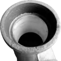
Steel + PP-R lining. Cold and hot water. CJ/T 137-2008.
Explore individual product photographs, size variants and technical data directly on this page.
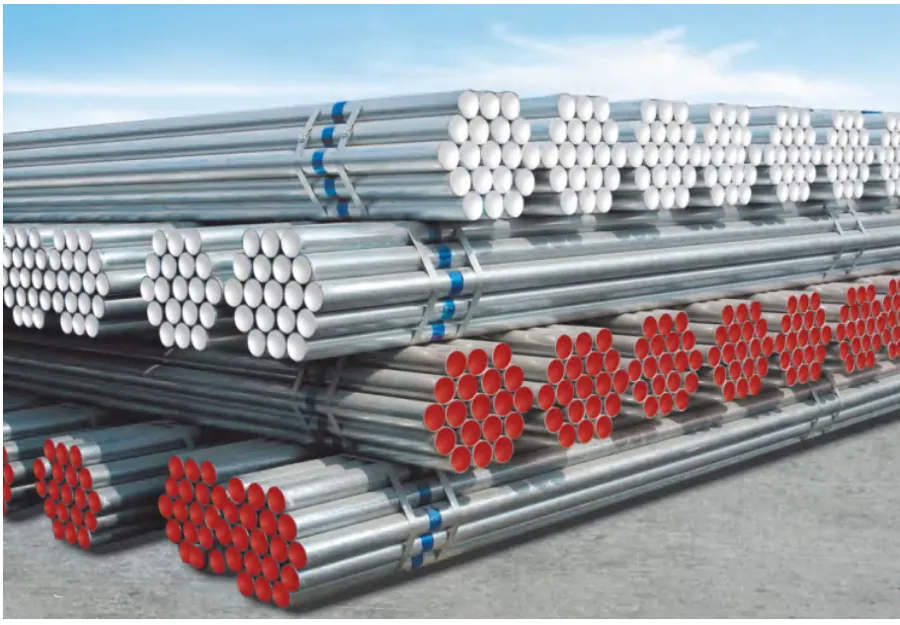
The range includes the following product families. Dimensions and operating limits depend on the selected series and product configuration.
| Parameter | Value |
|---|---|
| Standard | GB/T 28897-2021 |
| Pipe length | 6 m |
| PE lining maximum temperature | 40 °C |
| PE-RT lining maximum temperature | 70 °C |
| Lined pipe working pressure | ≤1.6 MPa |


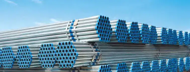

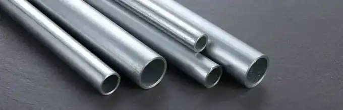
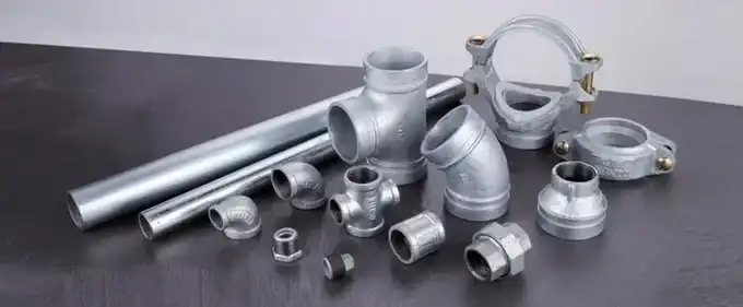



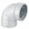
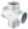
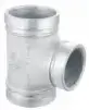
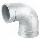


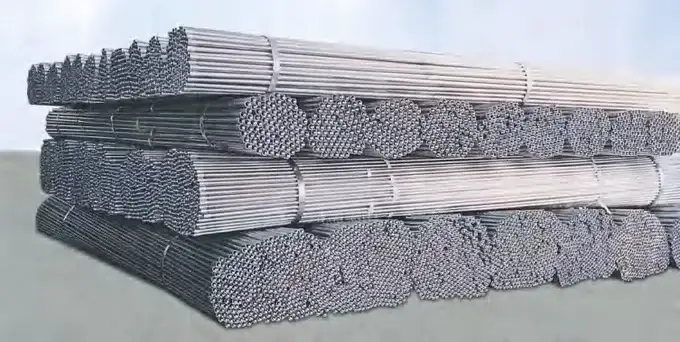



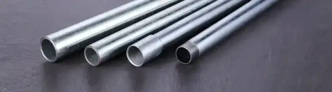
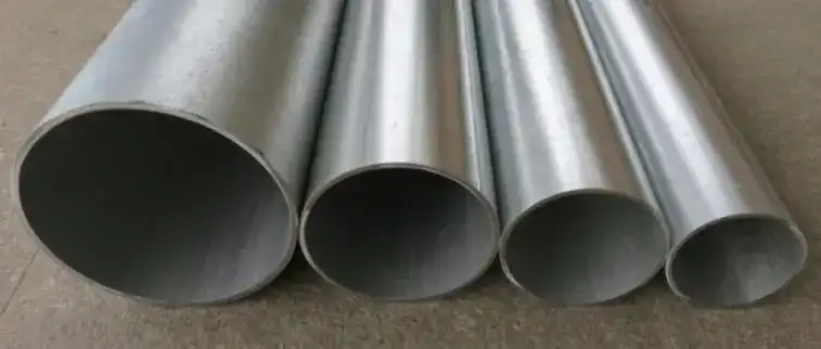
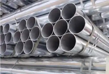
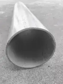
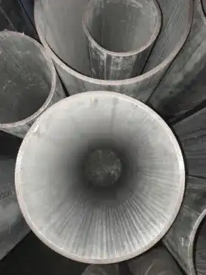
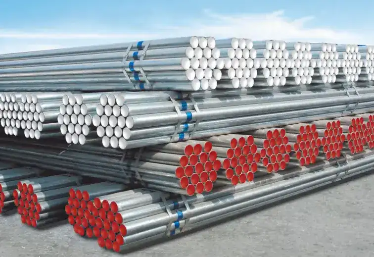
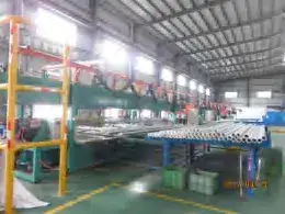
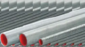
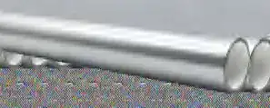
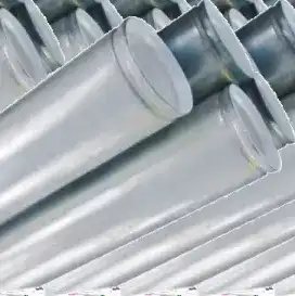


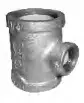

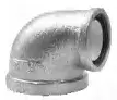
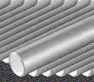
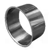
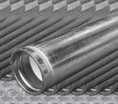
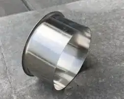
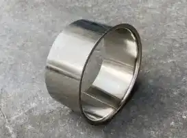
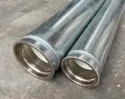
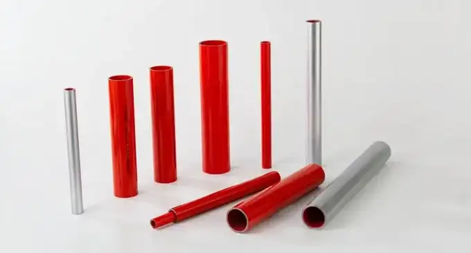
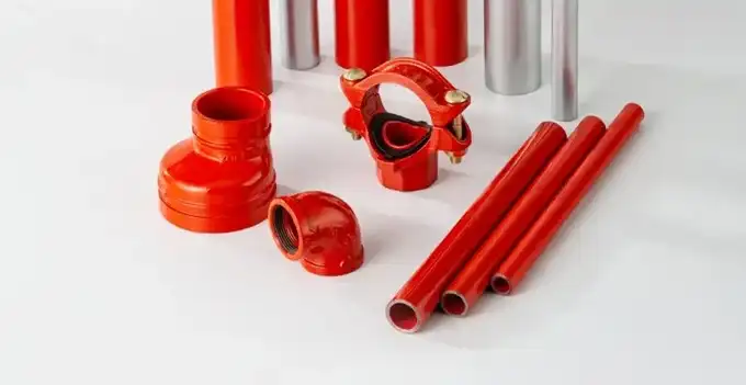

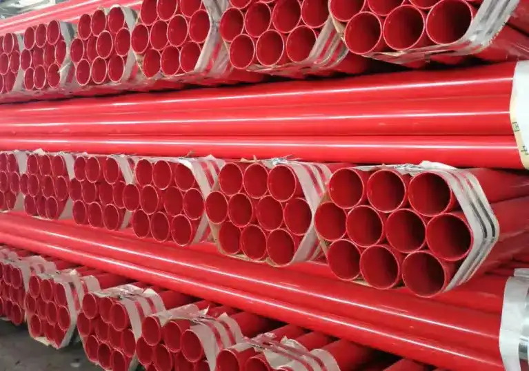
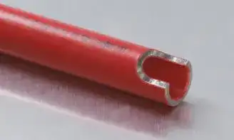

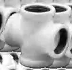



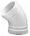

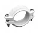
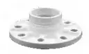
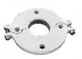
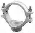
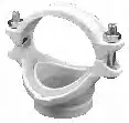
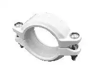


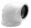




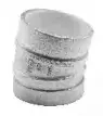
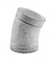
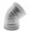
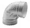
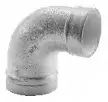


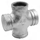

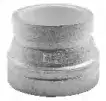
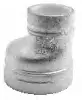


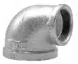


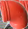
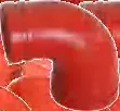



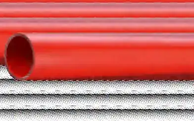
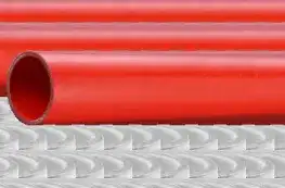


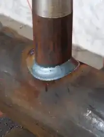
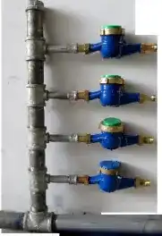

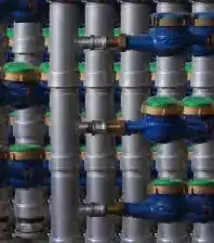
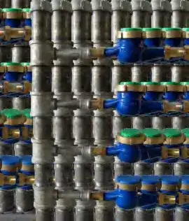
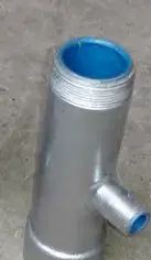
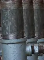
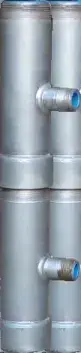
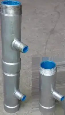
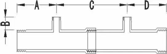
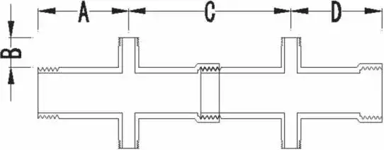
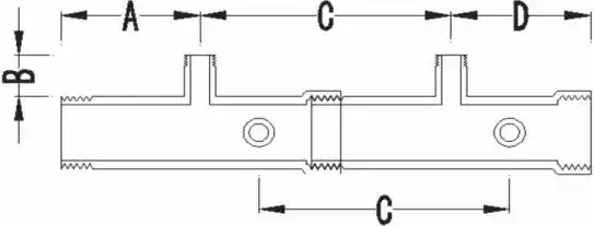
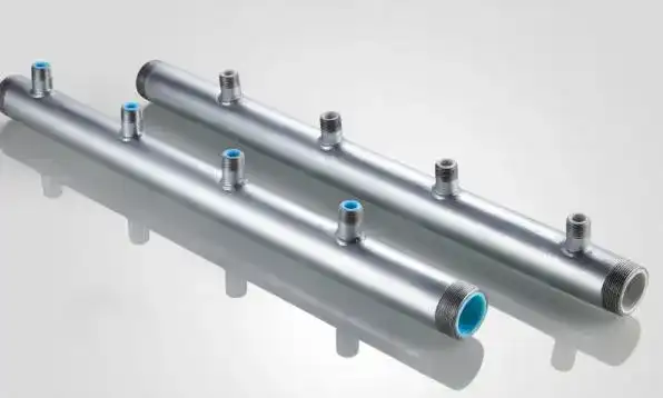
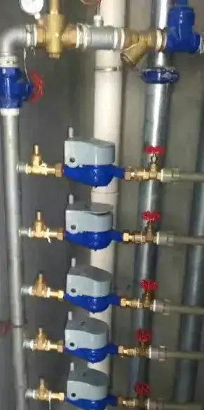
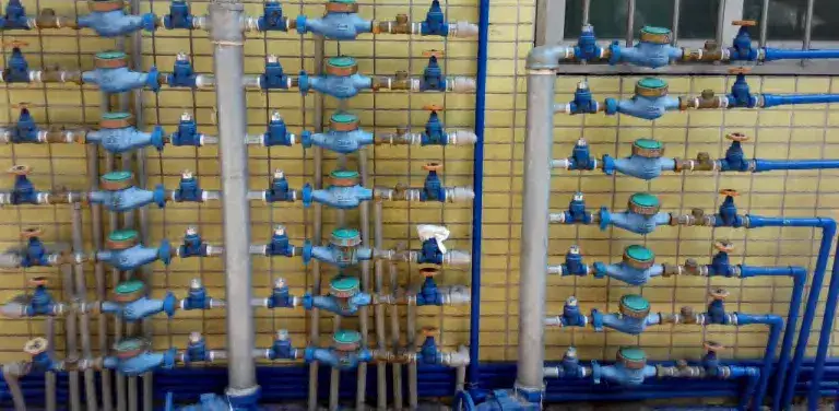
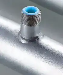
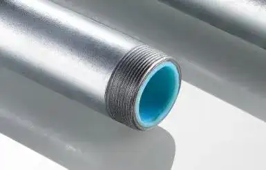
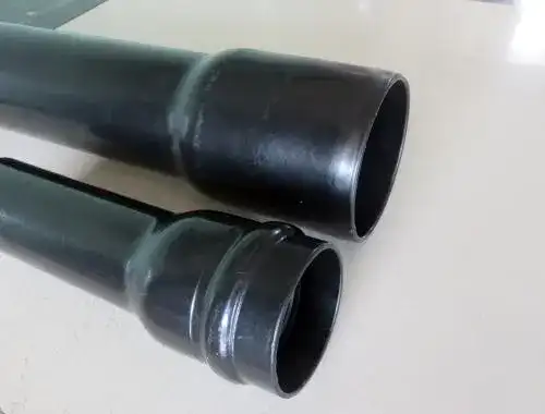
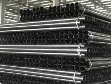
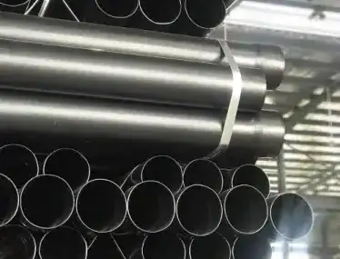
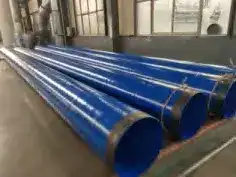
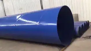
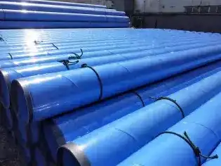
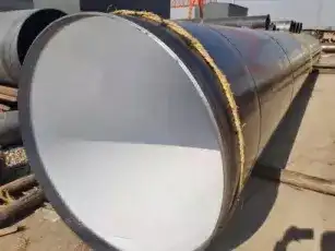
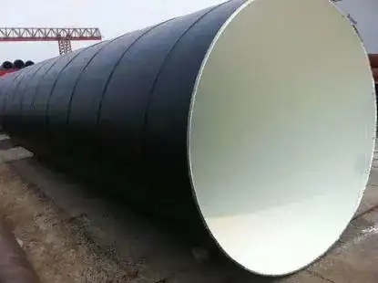
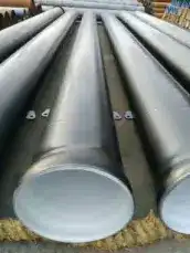
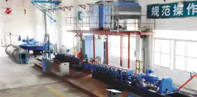
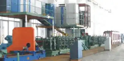
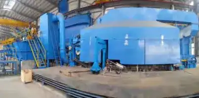
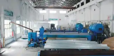
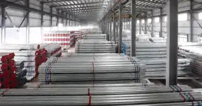
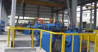
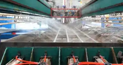
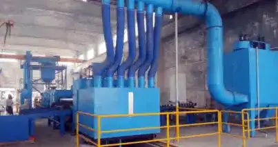
Catalogue 2024.06 · quotation 2024.04.23. The catalogue and quotation cover different size ranges. The tables below retain the catalogue dimensions. Photographs identify the product family, not every diameter.
Steel + PP-R lining. Cold and hot water. CJ/T 137-2008.
Steel base pipe + PE coating. DN15–DN300; catalogue length 6000 +20 mm.
Coated steel conduit for cable protection. Coating thickness ≥300 μm.
Steel + PE or EP coating. DN200–DN2400; standard length 12 m.
Source: LESSO Walton product manual 2024.06, pp. 15–36. Quotation: 2024.04.23.
Expand the product family to view its listed models and dimensions.
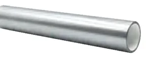
| Diameter (mm) | Size (in) | Lining thickness (mm) | Length (m) |
|---|---|---|---|
| 15 | 1/2 | 1.5 ±0.2 | 6 (+0.015) |
| 20 | 3/4 | 1.5 ±0.2 | 6 (+0.015) |
| 25 | 1 | 1.5 ±0.2 | 6 (+0.015) |
| 32 | 1-1/4 | 1.5 ±0.2 | 6 (+0.015) |
| 40 | 1-1/2 | 1.5 ±0.2 | 6 (+0.015) |
| 50 | 2 | 1.5 ±0.2 | 6 (+0.015) |
| 65 | 2-1/2 | 1.5 ±0.2 | 6 (+0.015) |
| 80 | 3 | 2.0 ±0.2 | 6 (+0.015) |
| 100 | 4 | 2.0 ±0.2 | 6 (+0.015) |
| 125 | 5 | 2.0 ±0.2 | 6 (+0.015) |
| 150 | 6 | 2.5 ±0.2 | 6 (+0.015) |
| 200 | 8 | 2.5 ±0.2 | 6 (+0.015) |
| 250 | 10 | 3.0 ±0.5 | 6 (+0.015) |
| 300 | 12 | 3.0 ±0.5 | 6 (+0.015) |
| Diameter (mm) | Size (in) | Material / configuration | Design pressure (MPa) | Long-term temperature (°C) | Length (m) |
|---|---|---|---|---|---|
| 15 | 1/2 | PE | ≤1.6 | ≤40 | 6 |
| 20 | 3/4 | PE | ≤1.6 | ≤40 | 6 |
| 25 | 1 | PE | ≤1.6 | ≤40 | 6 |
| 32 | 1-1/4 | PE | ≤1.6 | ≤40 | 6 |
| 40 | 1-1/2 | PE | ≤1.6 | ≤40 | 6 |
| 50 | 2 | PE | ≤1.6 | ≤40 | 6 |
| 65 | 2-1/2 | PE | ≤1.6 | ≤40 | 6 |
| 80 | 3 | PE | ≤1.6 | ≤40 | 6 |
| 100 | 4 | PE | ≤1.6 | ≤40 | 6 |
| 125 | 5 | PE | ≤1.6 | ≤40 | 6 |
| 150 | 6 | PE | ≤1.6 | ≤40 | 6 |
| 200 | 8 | PE | ≤1.6 | ≤40 | 6 |
| 250 | 10 | PE | ≤1.6 | ≤40 | 6 |
| 300 | 12 | PE | ≤1.6 | ≤40 | 6 |
Types I / II; grooved versions are listed from DN50 to DN300. Standard: GB/T 28897-2021.
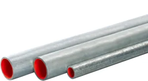
| Diameter (mm) | Size (in) | Material / configuration | Design pressure (MPa) | Long-term temperature (°C) | Length (m) |
|---|---|---|---|---|---|
| 15 | 1/2 | PE-RT | ≤1.6 | ≤70 | 6 |
| 20 | 3/4 | PE-RT | ≤1.6 | ≤70 | 6 |
| 25 | 1 | PE-RT | ≤1.6 | ≤70 | 6 |
| 32 | 1-1/4 | PE-RT | ≤1.6 | ≤70 | 6 |
| 40 | 1-1/2 | PE-RT | ≤1.6 | ≤70 | 6 |
| 50 | 2 | PE-RT | ≤1.6 | ≤70 | 6 |
| 65 | 2-1/2 | PE-RT | ≤1.6 | ≤70 | 6 |
| 80 | 3 | PE-RT | ≤1.6 | ≤70 | 6 |
| 100 | 4 | PE-RT | ≤1.6 | ≤70 | 6 |
| 125 | 5 | PE-RT | ≤1.6 | ≤70 | 6 |
| 150 | 6 | PE-RT | ≤1.6 | ≤70 | 6 |
| 200 | 8 | PE-RT | ≤1.6 | ≤70 | 6 |
| 250 | 10 | PE-RT | ≤1.6 | ≤70 | 6 |
| 300 | 12 | PE-RT | ≤1.6 | ≤70 | 6 |
Types I / II; grooved versions are listed from DN50 to DN300. Standard: GB/T 28897-2021.
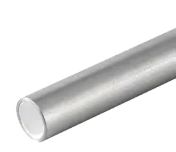
| Outside diameter (mm) | Size (in) | Wall thickness (mm) | Pieces per bundle | Length (m) |
|---|---|---|---|---|
| 76 | 2-1/2 | 4 | 37 | 6 |
| 89 | 3 | 4 | 19 | 6 |
| 114.3 | 4 | 4 | 19 | 6 |
| 159 | 6 | 4.5 | 10 | 6 |
| 168 | 6 | 5 | 10 | 6 |
| 219 | 8 | 6 | 7 | 6 |
| 273 | 10 | 7 | 3 | 6 |
| 325 | 12 | 8 | 3 | 6 |
Seamless composite range: rated working pressure ≤2.5 MPa; cold water ≤40 °C / PE-RT hot-water lining ≤70 °C.
| Diameter (mm) | Size (in) | Pieces per carton |
|---|---|---|
| 50 | 2 | 300 |
| 65 | 2-1/2 | 300 |
| 80 | 3 | 200 |
| 100 | 4 | 100 |
| 125 | 5 | 60 |
| 150 | 6 | 60 |
| 200 | 8 | 30 |
| 250 | 10 | 10 |
| 300 | 12 | 5 |
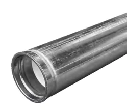
| Diameter (mm) | Size (in) | Wall thickness (mm) | Pieces per bundle | Length (m) |
|---|---|---|---|---|
| 50 | 2 | 3.5 | 37 | 6 |
| 65 | 2-1/2 | 3.75 | 37 | 6 |
| 80 | 3 | 3.75 | 19 | 6 |
| 100 | 4 | 3.75 | 19 | 6 |
| 125 | 5 | 3.75 | 10 | 6 |
| 150 | 6 | 4.25 | 10 | 6 |
| 200 | 8 | 5.5 | 7 | 6 |
| 250 | 10 | 6 | 3 | 6 |
| 300 | 12 | 6 | 3 | 6 |
| Diameter (mm) | Size (in) | Design pressure (MPa) | Length (m) |
|---|---|---|---|
| 15 | 1/2 | ≤1.6 | 6 |
| 20 | 3/4 | ≤1.6 | 6 |
| 25 | 1 | ≤1.6 | 6 |
| 32 | 1-1/4 | ≤1.6 | 6 |
| 40 | 1-1/2 | ≤1.6 | 6 |
| 50 | 2 | ≤1.6 | 6 |
| 65 | 2-1/2 | ≤1.6 | 6 |
| 80 | 3 | ≤1.6 | 6 |
| 100 | 4 | ≤1.6 | 6 |
| 125 | 5 | ≤1.6 | 6 |
| 150 | 6 | ≤1.6 | 6 |
| 200 | 8 | ≤1.6 | 6 |
| 250 | 10 | ≤1.6 | 6 |
| 300 | 12 | ≤1.6 | 6 |
Inner and outer coating; GB/T 5135.20-2010.
| Model | Diameter (mm) | Branch diameter (mm) | A (mm) | B (mm) | C (mm) | D (mm) |
|---|---|---|---|---|---|---|
| DN40*190*15 | 40 | 15 | 105 | 35 | 190 | 105 |
| DN40*190*20 | 40 | 20 | 105 | 35 | 190 | 105 |
| DN40*190*25 | 40 | 25 | 105 | 35 | 190 | 105 |
| DN50*190*15 | 50 | 15 | 105 | 35 | 190 | 105 |
| DN50*190*20 | 50 | 20 | 105 | 35 | 190 | 105 |
| DN50*190*25 | 50 | 25 | 105 | 35 | 190 | 105 |
| DN65*190*15 | 65 | 15 | 105 | 35 | 190 | 105 |
| DN65*190*20 | 65 | 20 | 105 | 35 | 190 | 105 |
| DN65*190*25 | 65 | 25 | 105 | 35 | 190 | 105 |
Standard, 180° rib and 90° angle versions; Q/LSWT 10-2022.
| Model | Diameter (mm) | Branch diameter (mm) | A (mm) | B (mm) | C (mm) | D (mm) |
|---|---|---|---|---|---|---|
| DN40*160*15/20 | 40 | 15 / 20 | 70 | 35 | 160 | 145 |
| DN40*170*15/20 | 40 | 15 / 20 | 70 | 35 | 170 | 155 |
| DN40*185*15/20 | 40 | 15 / 20 | 70 | 35 | 185 | 170 |
| DN50*160*15/20 | 50 | 15 / 20 | 70 | 35 | 160 | 145 |
| DN50*170*15/20 | 50 | 15 / 20 | 70 | 35 | 170 | 155 |
| DN50*185*15/20 | 50 | 15 / 20 | 70 | 35 | 185 | 170 |
| DN50*185*25 | 50 | 25 | 70 | 35 | 185 | 170 |
| DN65*160*15/20 | 65 | 15 / 20 | 70 | 35 | 160 | 145 |
| DN65*185*15/20 | 65 | 15 / 20 | 70 | 35 | 185 | 170 |
| DN65*185*25 | 65 | 25 | 70 | 35 | 185 | 170 |
Standard and 180° layouts; standard assemblies for 2–6 households. Q/LSWT 10-2022.
| Photo | Model | Product configuration |
|---|---|---|
| 90 | 90° elbow | |
| 120 | 45° Elbow | |
| 130 | Tee | |
| 180 | Cross | |
| 291 | Cap | |
| 280 | Male threaded connector | |
| 270 | Female threaded connector | |
| 330 | Union | |
| 90R | 90° reducing elbow | |
| 130R | Reducing tee | |
| 180R | Reducing cross | |
| 240 | Reducing coupling | |
| 241 | Reducing bushing |
| Photo | Model | Product configuration |
|---|---|---|
| 90 | 90° elbow | |
| 120 | 45° Elbow | |
| 130 | Tee | |
| 180 | Cross | |
| 291 | Cap | |
| 280 | Male threaded connector | |
| 270 | Female threaded connector | |
| 330 | Union | |
| 90R | 90° reducing elbow | |
| 130R | Reducing tee | |
| 180R | Reducing cross | |
| 240 | Reducing coupling | |
| 241 | Reducing bushing |
| Photo | Model | Product configuration |
|---|---|---|
| 105 | 11.25° elbow | |
| 110 | 22.5° elbow | |
| 120 | 45° Elbow | |
| 90 | 90° elbow | |
| 90R | 90° reducing elbow | |
| 130 | Tee | |
| 180 | Cross | |
| 130R | Reducing tee | |
| 131R | Threaded tee | |
| 181 | Threaded cross | |
| 240 | Grooved reducing coupling | |
| 230 | Eccentric grooved reducer | |
| 230N | Eccentric grooved female threaded reducer | |
| 240N | Grooved female threaded reducer | |
| 321 | Adapter flange | |
| 321G | Weld flange | |
| 1G | Rigid coupling | |
| 1N | Flexible coupling | |
| 300 | End cap | |
| 3J | Threaded mechanical tee | |
| 3G | Grooved mechanical tee |
| Photo | Model | Product configuration |
|---|---|---|
| 90 | 90° elbow | |
| 120 | 45° Elbow | |
| 130 | Tee | |
| 180 | Cross | |
| 291 | Cap | |
| 280 | Male threaded connector | |
| 270 | Female threaded connector | |
| 330 | Union | |
| 90R | 90° reducing elbow | |
| 130R | Reducing tee | |
| 180R | Reducing cross | |
| 240 | Reducing coupling | |
| 241 | Reducing bushing |
| Photo | Model | Product configuration |
|---|---|---|
| 105 | 11.25° elbow | |
| 110 | 22.5° elbow | |
| 120 | 45° Elbow | |
| 90 | 90° elbow | |
| 90R | 90° reducing elbow | |
| 130 | Tee | |
| 180 | Cross | |
| 130R | Reducing tee | |
| 131R | Threaded tee | |
| 181 | Threaded cross | |
| 240 | Grooved reducing coupling | |
| 230 | Eccentric grooved reducer | |
| 230N | Eccentric grooved female threaded reducer | |
| 240N | Grooved female threaded reducer | |
| 321 | Adapter flange | |
| 321G | Weld flange | |
| 1G | Rigid coupling | |
| 1N | Flexible coupling | |
| 300 | End cap | |
| 3J | Threaded mechanical tee | |
| 3G | Grooved mechanical tee |
| Photo | Model | Product configuration |
|---|---|---|
| 90 | 90° elbow | |
| 120 | 45° Elbow | |
| 130 | Tee | |
| 180 | Cross | |
| 291 | Cap | |
| 280 | Male threaded connector | |
| 270 | Female threaded connector | |
| 330 | Union | |
| 90R | 90° reducing elbow | |
| 130R | Reducing tee | |
| 180R | Reducing cross | |
| 240 | Reducing coupling | |
| 241 | Reducing bushing |
Contact LESSO Armenia for pricing, options, sizes and delivery.
Original PDF files