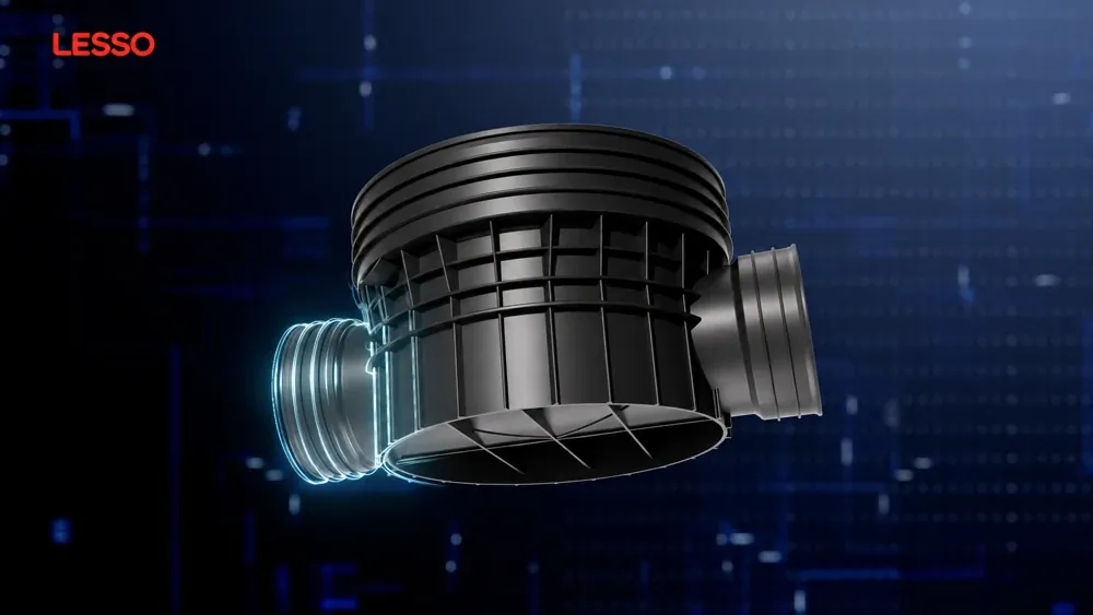
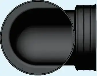
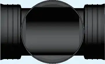
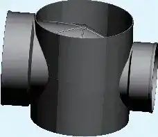
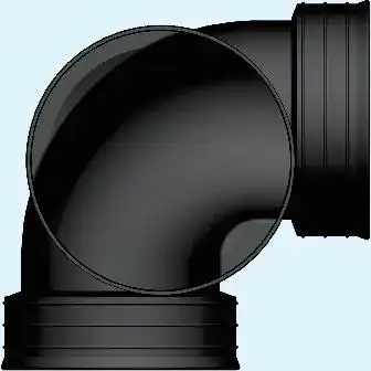
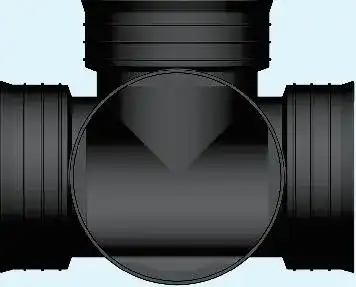
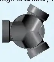
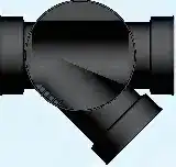
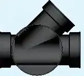
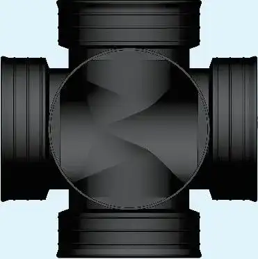
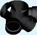
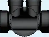
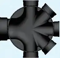
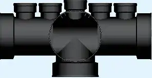
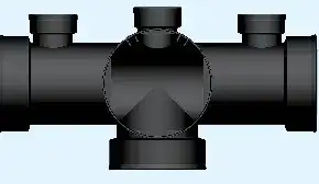
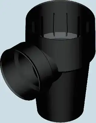
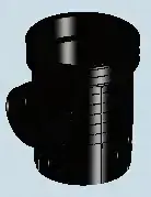
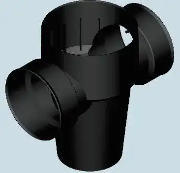
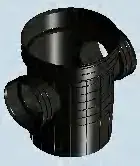
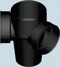
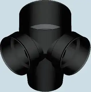
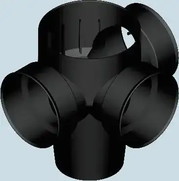
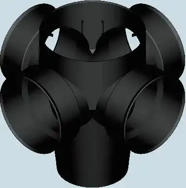
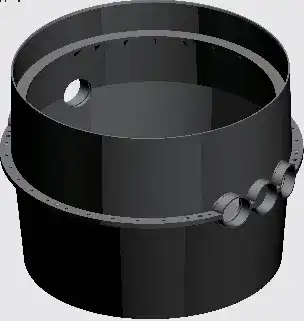
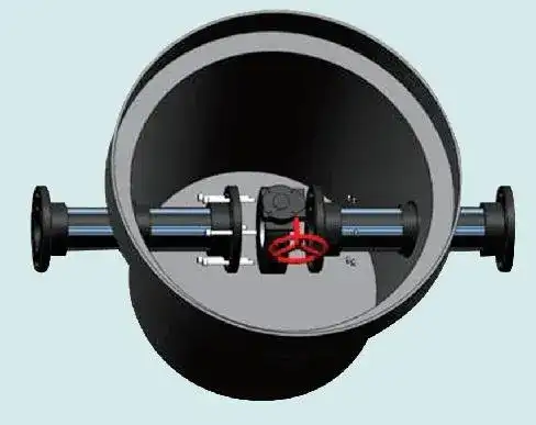
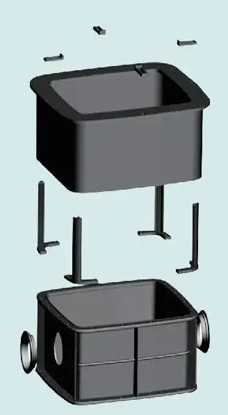
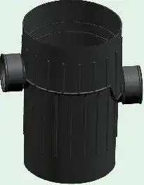
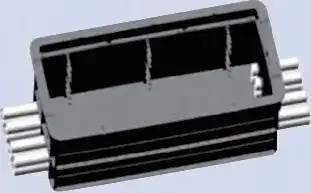
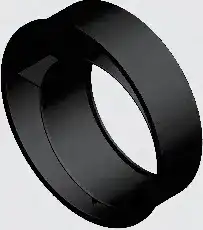
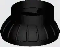
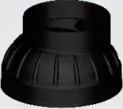
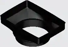
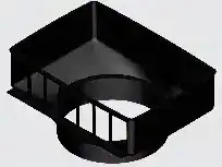
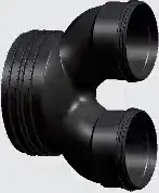
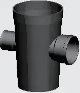
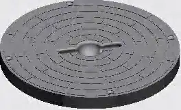
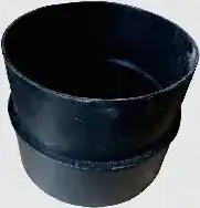
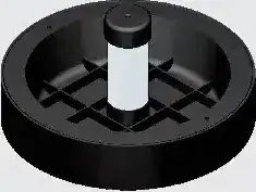
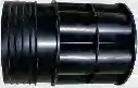
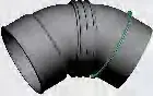
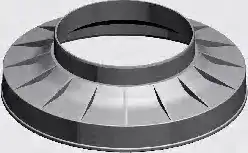
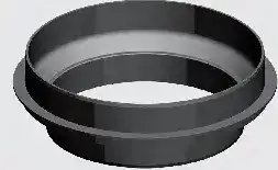
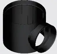
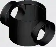
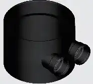
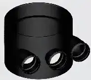
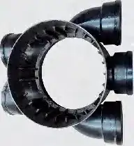
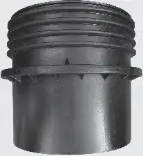
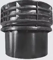
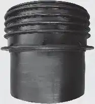
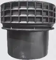
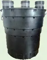
The film shows a base with opposite pipe connections, external reinforcement ribs and support ribs beneath the chamber.
LESSO film · 1:40
02
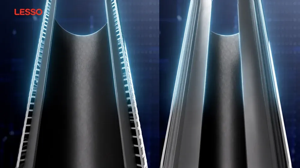
Two wall constructions
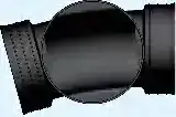
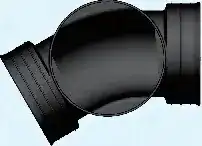
Two constructions are shown: HDPE spiral structured-wall pipe and PVC-U double-layer axial hollow-wall pipe.
LESSO film · 2:30
03
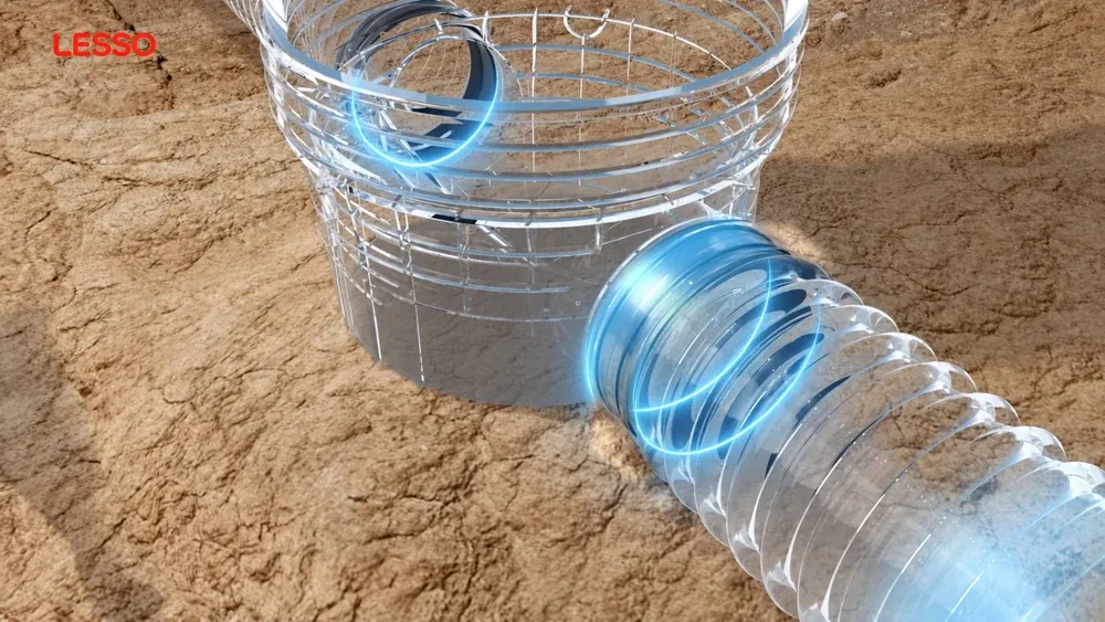
The pipe-to-chamber joint
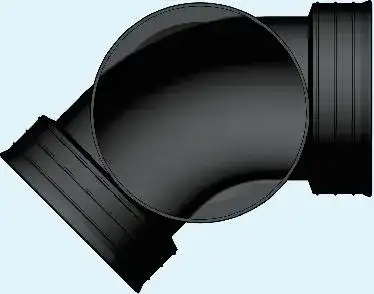
The transparent view shows the pipe entering the chamber socket and the sealing area around the joint.
LESSO film · 2:50
04
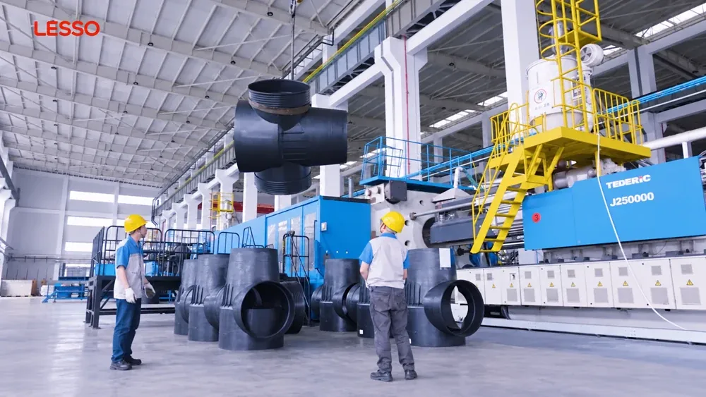
Handling in the factory
The factory sequence shows chamber-base components being handled before installation.
LESSO film · 1:07
05
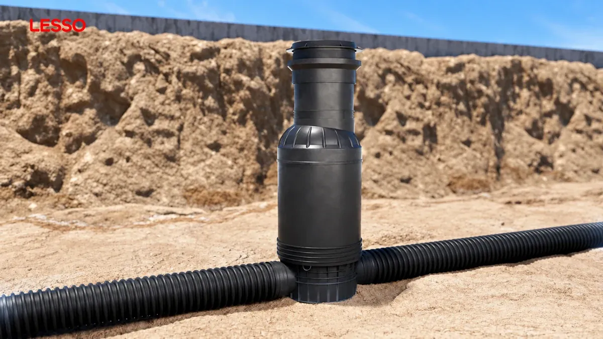
The assembled system on site
At 1:07, the assembled chamber, upper transition and connected corrugated pipes are shown in an excavated trench.
LESSO01 / 05
LESSO film · 1:10
Plastic inspection chambers:base model range
Type I chamber bases include trough and silt series. The 633 unique published model variants are presented below. Model notation identifies the nominal wellhole and branch connections; A denotes an inner-diameter series and B an outer-diameter series.
L101 · Starting trough chamber base
Model as published
Wellhole encoded(mm)
Branch notation encoded
L101-200×150A
200
150A
L101-200×160B
200
160B
L101-200×200B
200
200B
L101-315×110B
315
110B
L101-315×160B
315
160B
L101-315×200A
315
200A
L101-315×200B
315
200B
L101-315×225A
315
225A
L101-315×250B
315
250B
L101-315×300A
315
300A
L101-315×315B
315
315B
L101-400×200A
400
200A
L101-400×200B
400
200B
L101-400×225A
400
225A
L101-400×250B
400
250B
L101-400×300A
400
300A
L101-400×315B
400
315B
L101-400×400B
400
400B
L101-400×400A
400
400A
L101-450×200A
450
200A
L101-450×200B
450
200B
L101-450×225A
450
225A
L101-450×250B
450
250B
L101-450×300A
450
300A
L101-450×315B
450
315B
L101-450×400A
450
400A
L101-500×300A
500
300A
L101-500×315B
500
315B
L101-500×400B
500
400B
L101-500×400A
500
400A
L101-500×500A
500
500A
L101-600×200B
600
200B
L101-600×225A
600
225A
L101-600×300A
600
300A
L101-600×315B
600
315B
L101-600×400B
600
400B
L101-600×400A
600
400A
L101-600×500A
600
500A
L101-600×500B
600
500B
L101-600×600A
600
600A
L101-630×200B
630
200B
L101-630×225A
630
225A
L101-630×300A
630
300A
L101-630×315B
630
315B
L101-630×400B
630
400B
L101-630×400A
630
400A
L101-630×500B
630
500B
L101-630×500A
630
500A
L101-630×600A
630
600A
L101-700×300A
700
300A
L101-700×315B
700
315B
L101-700×500A
700
500A
L101-800×300A
800
300A
L102 · Straight-way trough chamber base
Model as published
Wellhole encoded(mm)
Branch notation encoded
L102-200×150A
200
150A
L102-200×160B
200
160B
L102-200×200B
200
200B
L102-315×150A
315
150A
L102-315×160B
315
160B
L102-315×200B
315
200B
L102-315×200A
315
200A
L102-315×225A
315
225A
L102-315×250B
315
250B
L102-315×300A
315
300A
L102-315×315B
315
315B
L102-400×200A
400
200A
L102-400×200B
400
200B
L102-400×225A
400
225A
L102-400×250B
400
250B
L102-400×300A
400
300A
L102-400×315B
400
315B
L102-400×400B
400
400B
L102-400×400A
400
400A
L102-450×200B
450
200B
L102-450×200A
450
200A
L102-450×225A
450
225A
L102-450×300A
450
300A
L102-450×315B
450
315B
L102-450×400B
450
400B
L102-450×400A
450
400A
L102-500×300A
500
300A
L102-500×315B
500
315B
L102-500×400A
500
400A
L102-500×400B
500
400B
L102-500×500A
500
500A
L102-600×200B
600
200B
L102-600×200A
600
200A
L102-600×225A
600
225A
L102-600×300A
600
300A
L102-600×315B
600
315B
L102-600×400A
600
400A
L102-600×400B
600
400B
L102-600×500B
600
500B
L102-600×500A
600
500A
L102-600×600A
600
600A
L102-630×200B
630
200B
L102-630×200A
630
200A
L102-630×225A
630
225A
L102-630×300A
630
300A
L102-630×315B
630
315B
L102-630×400B
630
400B
L102-630×400A
630
400A
L102-630×500A
630
500A
L102-630×500B
630
500B
L102-630×600A
630
600A
L102-700×200B
700
200B
L102-700×300A
700
300A
L102-700×315B
700
315B
L102-700×400A
700
400A
L102-700×500A
700
500A
L102-700×600A
700
600A
L102-800×300A
800
300A
L102-800×400A
800
400A
L102-800×500A
800
500A
L102-800×600A
800
600A
L102-800×800A
800
800A
L102-1000×300A
1000
300A
L102-1000×400A
1000
400A
L102-1000×500A
1000
500A
L102-1000×600A
1000
600A
L102-1000×700A
1000
700A
L102-1000×800A
1000
800A
L102-1000×1000A
1000
1000A
L102-1200×300A
1200
300A
L102-1200×400A
1200
400A
L102-1200×500A
1200
500A
L102-1200×600A
1200
600A
L102-1200×700A
1200
700A
L102-1200×800A
1200
800A
L102-1200×1000A
1200
1000A
L103 · Reducing straight-way trough chamber base
Model as published
Wellhole encoded(mm)
Branch notation encoded
L103-500×400A/300A
500
400A/300A
L103-500×500A/400A
500
500A/400A
L103-600×200B/110B
600
200B/110B
L103-630×200B/110B
630
200B/110B
L104 · 15° elbow trough chamber base
Model as published
Wellhole encoded(mm)
Branch notation encoded
L104-315×250B
315
250B
L104-315×300A
315
300A
L104-500×400A
500
400A
L105 · 30° elbow trough chamber base
Model as published
Wellhole encoded(mm)
Branch notation encoded
L105-315×225A
315
225A
L105-400×300A
400
300A
L105-400×400A
400
400A
L105-450×300A
450
300A
L105-450×400A
450
400A
L105-600×500A
600
500A
L105-630×500A
630
500A
L106 · 45° elbow trough chamber base
Model as published
Wellhole encoded(mm)
Branch notation encoded
L106-200×150A
200
150A
L106-200×160B
200
160B
L106-200×200B
200
200B
L106-315×110B
315
110B
L106-315×150A
315
150A
L106-315×160B
315
160B
L106-315×200B
315
200B
L106-315×200A
315
200A
L106-315×225A
315
225A
L106-315×250B
315
250B
L106-315×300A
315
300A
L106-315×315B
315
315B
L106-400×200A
400
200A
L106-400×200B
400
200B
L106-400×225A
400
225A
L106-400×250B
400
250B
L106-400×300A
400
300A
L106-400×315B
400
315B
L106-400×400A
400
400A
L106-400×400B
400
400B
L106-450×200A
450
200A
L106-450×200B
450
200B
L106-450×225A
450
225A
L106-450×250B
450
250B
L106-450×300A
450
300A
L106-450×315B
450
315B
L106-450×400B
450
400B
L106-450×400A
450
400A
L106-500×300A
500
300A
L106-500×315B
500
315B
L106-500×400A
500
400A
L106-500×400B
500
400B
L106-500×500A
500
500A
L106-600×200A
600
200A
L106-600×200B
600
200B
L106-600×225A
600
225A
L106-600×300A
600
300A
L106-600×315B
600
315B
L106-600×400A
600
400A
L106-600×400B
600
400B
L106-600×500A
600
500A
L106-600×500B
600
500B
L106-600×600A
600
600A
L106-630×200B
630
200B
L106-630×200A
630
200A
L106-630×225A
630
225A
L106-630×300A
630
300A
L106-630×315B
630
315B
L106-630×400B
630
400B
L106-630×400A
630
400A
L106-630×500A
630
500A
L106-630×500B
630
500B
L106-630×600A
630
600A
L106-700×300A
700
300A
L106-700×400A
700
400A
L106-700×500A
700
500A
L106-700×600A
700
600A
L107 · 90° elbow trough chamber base
Model as published
Wellhole encoded(mm)
Branch notation encoded
L107-200×150A
200
150A
L107-200×160B
200
160B
L107-200×200B
200
200B
L107-315×110B
315
110B
L107-315×150A
315
150A
L107-315×160B
315
160B
L107-315×200A
315
200A
L107-315×200B
315
200B
L107-315×225A
315
225A
L107-315×250B
315
250B
L107-315×300A
315
300A
L107-315×315B
315
315B
L107-400×200B
400
200B
L107-400×200A
400
200A
L107-400×225A
400
225A
L107-400×250B
400
250B
L107-400×300A
400
300A
L107-400×315B
400
315B
L107-400×400A
400
400A
L107-400×400B
400
400B
L107-450×200A
450
200A
L107-450×200B
450
200B
L107-450×225A
450
225A
L107-450×250B
450
250B
L107-450×300A
450
300A
L107-450×315B
450
315B
L107-450×400B
450
400B
L107-500×300A
500
300A
L107-500×315B
500
315B
L107-500×400A
500
400A
L107-500×400B
500
400B
L107-500×500A
500
500A
L107-600×200A
600
200A
L107-600×200B
600
200B
L107-600×225A
600
225A
L107-600×300A
600
300A
L107-600×315B
600
315B
L107-600×400B
600
400B
L107-600×400A
600
400A
L107-600×500B
600
500B
L107-600×500A
600
500A
L107-600×600A
600
600A
L107-630×200B
630
200B
L107-630×200A
630
200A
L107-630×225A
630
225A
L107-630×300A
630
300A
L107-630×315B
630
315B
L107-630×400B
630
400B
L107-630×400A
630
400A
L107-630×500B
630
500B
L107-630×500A
630
500A
L107-630×600A
630
600A
L107-700×200B
700
200B
L107-700×300A
700
300A
L107-700×400A
700
400A
L107-700×500A
700
500A
L107-700×600A
700
600A
L107-800×300A
800
300A
L107-800×400A
800
400A
L107-800×600A
800
600A
L107-800×800A
800
800A
L107-1000×300A
1000
300A
L107-1200×300A
1200
300A
L108 · 90° tee trough chamber base
Model as published
Wellhole encoded(mm)
Branch notation encoded
L108-200×150A
200
150A
L108-200×160B
200
160B
L108-200×200B
200
200B
L108-200×200B×110B
200
200B×110B
L108-315×110B
315
110B
L108-315×150A
315
150A
L108-315×160B
315
160B
L108-315×200B
315
200B
L108-315×200A
315
200A
L108-315×225A
315
225A
L108-315×250B
315
250B
L108-315×300A
315
300A
L108-315×315B
315
315B
L108-400×200A
400
200A
L108-400×200B
400
200B
L108-400×225A
400
225A
L108-400×250B
400
250B
L108-400×300A
400
300A
L108-400×315B
400
315B
L108-400×400B
400
400B
L108-400×400A
400
400A
L108-450×200B
450
200B
L108-450×200A
450
200A
L108-450×225A
450
225A
L108-450×300A
450
300A
L108-450×315B
450
315B
L108-450×400A
450
400A
L108-450×400B
450
400B
L108-500×300A
500
300A
L108-500×315B
500
315B
L108-500×400B
500
400B
L108-500×400A
500
400A
L108-500×500A
500
500A
L108-600×200B
600
200B
L108-600×200A
600
200A
L108-600×225A
600
225A
L108-600×300A
600
300A
L108-600×315B
600
315B
L108-600×400A
600
400A
L108-600×400B
600
400B
L108-600×500A
600
500A
L108-600×500B
600
500B
L108-600×600A
600
600A
L108-630×200A
630
200A
L108-630×200B
630
200B
L108-630×225A
630
225A
L108-630×300A
630
300A
L108-630×315B
630
315B
L108-630×400A
630
400A
L108-630×400B
630
400B
L108-630×500B
630
500B
L108-630×500A
630
500A
L108-630×600A
630
600A
L108-700×200B
700
200B
L108-700×300A
700
300A
L108-700×400A
700
400A
L108-700×500A
700
500A
L108-700×600A
700
600A
L108-800×300A
800
300A
L108-800×400A
800
400A
L108-800×500A
800
500A
L108-800×600A
800
600A
L108-800×800A
800
800A
L108-1000×300A
1000
300A
L108-1000×400A
1000
400A
L108-1000×500A
1000
500A
L108-1000×600A
1000
600A
L108-1000×800A
1000
800A
L108-1000×1000A
1000
1000A
L108-1200×300A
1200
300A
L108-1200×400A
1200
400A
L108-1200×500A
1200
500A
L108-1200×600A
1200
600A
L108-1200×700A
1200
700A
L108-1200×800A
1200
800A
L108-1200×1000A
1200
1000A
L109 · 120° tee trough chamber base
Model as published
Wellhole encoded(mm)
Branch notation encoded
L109-400×300A
400
300A
L109-450×300A
450
300A
L109-500×300A
500
300A
L109-500×400A
500
400A
L111 · 45° left-oblique tee trough base
Model as published
Wellhole encoded(mm)
Branch notation encoded
L111-315×200B
315
200B
L111-500×300A
500
300A
L112 · 45° right-oblique tee trough base
Model as published
Wellhole encoded(mm)
Branch notation encoded
L112-315×110B
315
110B
L112-315×160B
315
160B
L112-315×200B
315
200B
L112-315×225A×160B
315
225A×160B
L112-500×300A
500
300A
L114 · 90° four-way trough chamber base
Model as published
Wellhole encoded(mm)
Branch notation encoded
L114-200×150A
200
150A
L114-200×160B
200
160B
L114-315×160B
315
160B
L114-315×200B
315
200B
L114-315×225A
315
225A
L114-315×250B
315
250B
L114-400×225A
400
225A
L114-400×300A
400
300A
L114-400×315B
400
315B
L114-400×400A
400
400A
L114-450×225A
450
225A
L114-450×300A
450
300A
L114-450×315B
450
315B
L114-450×400A
450
400A
L114-600×300A
600
300A
L114-600×400A
600
400A
L114-630×300A
630
300A
L114-630×400A
630
400A
L114-1000×300A
1000
300A
L114-1200×300A
1200
300A
L115 · 45° oblique four-way trough base
Model as published
Wellhole encoded(mm)
Branch notation encoded
L115-315×200B
315
200B
L115-315×225×160B
315
225×160B
L115-500×300A
500
300A
L115-600×200B×160B×110B
600
200B×160B×110B
L115-630×200B×160B×110B
630
200B×160B×110B
L120 · Two-pipe convergence straight-way base
Model as published
Wellhole encoded(mm)
Branch notation encoded
L120-315×200A×160B×2
315
200A×160B×2
L121 · Six-way trough chamber base
Model as published
Wellhole encoded(mm)
Branch notation encoded
L121-500×250B×160B×5
500
250B×160B×5
L160 · Five-pipe convergence tee base
Model as published
Wellhole encoded(mm)
Branch notation encoded
L160-400×250B×150A×5
400
250B×150A×5
L160-400×300A×150A×5
400
300A×150A×5
L160-400×400A×150A×5
400
400A×150A×5
L198 · Three-pipe convergence straight-way base
Model as published
Wellhole encoded(mm)
Branch notation encoded
L198-400×250A×150A×3
400
250A×150A×3
L198-400×300A×150A×3
400
300A×150A×3
L198-400×400A×150A×3
400
400A×150A×3
N101 · Starting silt chamber base
Model as published
Wellhole encoded(mm)
Branch notation encoded
N101-200×110B
200
110B
N101-200×160B
200
160B
N101-200×200B
200
200B
N101-315×150A
315
150A
N101-315×160B
315
160B
N101-315×200B
315
200B
N101-315×200A
315
200A
N101-315×225A
315
225A
N101-315×250B
315
250B
N101-315×300A
315
300A
N101-315×315B
315
315B
N101-400×200A
400
200A
N101-400×225A
400
225A
N101-400×300A
400
300A
N101-400×315B
400
315B
N101-400×400B
400
400B
N101-400×400A
400
400A
N101-450×200A
450
200A
N101-450×225A
450
225A
N101-450×300A
450
300A
N101-450×315B
450
315B
N101-450×400A
450
400A
N101-450×400B
450
400B
N101-500×300A
500
300A
N101-500×400A
500
400A
N101-600×300A
600
300A
N101-600×315B
600
315B
N101-600×400B
600
400B
N101-600×400A
600
400A
N101-600×500B
600
500B
N101-600×500A
600
500A
N101-600×600A
600
600A
N101-630×300A
630
300A
N101-630×315B
630
315B
N101-630×400A
630
400A
N101-630×400B
630
400B
N101-630×500B
630
500B
N101-630×500A
630
500A
N101-630×600A
630
600A
N101-700×300A
700
300A
N101-700×400A
700
400A
N101-700×500A
700
500A
N101-700×600A
700
600A
N101-1000×300A
1000
300A
N101-1000×400A
1000
400A
N101-1000×500A
1000
500A
N101-1000×600A
1000
600A
N101-1000×700A
1000
700A
N101-1200×300A
1200
300A
N101-1200×400A
1200
400A
N101-1200×500A
1200
500A
N101-1200×600A
1200
600A
N101-1200×700A
1200
700A
N102 · Straight-way silt chamber base
Model as published
Wellhole encoded(mm)
Branch notation encoded
N102-200×160B
200
160B
N102-200×200B
200
200B
N102-315×110B
315
110B
N102-315×150A
315
150A
N102-315×200B
315
200B
N102-315×200A
315
200A
N102-315×225A
315
225A
N102-315×250B
315
250B
N102-315×300A
315
300A
N102-315×315B
315
315B
N102-400×225A
400
225A
N102-400×300A
400
300A
N102-400×315B
400
315B
N102-400×400B
400
400B
N102-400×400A
400
400A
N102-450×225A
450
225A
N102-450×300A
450
300A
N102-450×315B
450
315B
N102-450×400B
450
400B
N102-450×400A
450
400A
N102-500×300A
500
300A
N102-500×400A
500
400A
N102-600×300A
600
300A
N102-600×315B
600
315B
N102-600×400B
600
400B
N102-600×400A
600
400A
N102-600×500B
600
500B
N102-600×500A
600
500A
N102-600×600A
600
600A
N102-630×300A
630
300A
N102-630×315B
630
315B
N102-630×400A
630
400A
N102-630×400B
630
400B
N102-630×500A
630
500A
N102-630×500B
630
500B
N102-630×600A
630
600A
N102-700×300A
700
300A
N102-700×400A
700
400A
N102-700×500A
700
500A
N102-700×600A
700
600A
N102-1000×300A
1000
300A
N102-1000×400A
1000
400A
N102-1000×500A
1000
500A
N102-1000×600A
1000
600A
N102-1000×700A
1000
700A
N102-1000×800A
1000
800A
N102-1200×300A
1200
300A
N102-1200×400A
1200
400A
N102-1200×500A
1200
500A
N102-1200×600A
1200
600A
N102-1200×700A
1200
700A
N102-1200×800A
1200
800A
N106 · 45° elbow silt chamber base
Model as published
Wellhole encoded(mm)
Branch notation encoded
N106-315×225A
315
225A
N106-400×300A
400
300A
N106-400×400A
400
400A
N106-450×300A
450
300A
N106-450×400A
450
400A
N107 · 90° elbow silt chamber base
Model as published
Wellhole encoded(mm)
Branch notation encoded
N107-200×160B
200
160B
N107-200×200B
200
200B
N107-315×110B
315
110B
N107-315×150A
315
150A
N107-315×160B
315
160B
N107-315×200A
315
200A
N107-315×200B
315
200B
N107-315×225A
315
225A
N107-315×250B
315
250B
N107-315×300A
315
300A
N107-315×315B
315
315B
N107-400×300A
400
300A
N107-400×315B
400
315B
N107-400×400A
400
400A
N107-400×400B
400
400B
N107-450×300A
450
300A
N107-450×315B
450
315B
N107-450×400A
450
400A
N107-450×400B
450
400B
N107-500×300A
500
300A
N107-500×400A
500
400A
N107-600×300A
600
300A
N107-600×315B
600
315B
N107-600×400A
600
400A
N107-600×400B
600
400B
N107-600×500B
600
500B
N107-600×500A
600
500A
N107-600×600A
600
600A
N107-630×300A
630
300A
N107-630×315B
630
315B
N107-630×400A
630
400A
N107-630×400B
630
400B
N107-630×500A
630
500A
N107-630×500B
630
500B
N107-630×600A
630
600A
N107-700×300A
700
300A
N107-700×400A
700
400A
N107-700×500A
700
500A
N107-700×600A
700
600A
N107-1000×300A
1000
300A
N107-1000×400A
1000
400A
N107-1000×500A
1000
500A
N107-1000×600A
1000
600A
N107-1000×700A
1000
700A
N108 · 90° tee silt chamber base
Model as published
Wellhole encoded(mm)
Branch notation encoded
N108-200×160B
200
160B
N108-200×200B
200
200B
N108-315×150A
315
150A
N108-315×160B
315
160B
N108-315×200A
315
200A
N108-315×200B
315
200B
N108-315×225A
315
225A
N108-315×250B
315
250B
N108-315×300A
315
300A
N108-315×315B
315
315B
N108-400×225A
400
225A
N108-400×300A
400
300A
N108-400×315B
400
315B
N108-400×400A
400
400A
N108-400×400B
400
400B
N108-450×225A
450
225A
N108-450×300A
450
300A
N108-450×315B
450
315B
N108-450×400A
450
400A
N108-450×400B
450
400B
N108-500×300A
500
300A
N108-500×400A
500
400A
N108-600×300A
600
300A
N108-600×315B
600
315B
N108-600×400A
600
400A
N108-600×400B
600
400B
N108-600×500A
600
500A
N108-600×500B
600
500B
N108-600×600A
600
600A
N108-630×300A
630
300A
N108-630×315B
630
315B
N108-630×400B
630
400B
N108-630×400A
630
400A
N108-630×500B
630
500B
N108-630×500A
630
500A
N108-630×600A
630
600A
N108-700×300A
700
300A
N108-700×400A
700
400A
N108-700×500A
700
500A
N108-700×600A
700
600A
N108-1000×300A
1000
300A
N108-1000×400A
1000
400A
N108-1000×500A
1000
500A
N108-1000×600A
1000
600A
N108-1000×700A
1000
700A
N108-1200×300A
1200
300A
N108-1200×400A
1200
400A
N108-1200×500A
1200
500A
N108-1200×600A
1200
600A
N108-1200×700A
1200
700A
N114 · 90° four-way silt chamber base
Model as published
Wellhole encoded(mm)
Branch notation encoded
N114-200×160B
200
160B
N114-200×200B
200
200B
N114-315×160B
315
160B
N114-315×200A
315
200A
N114-315×225A
315
225A
N114-315×250B
315
250B
N114-315×300A
315
300A
N114-315×315B
315
315B
N114-400×225A
400
225A
N114-400×300A
400
300A
N114-400×315B
400
315B
N114-400×400B
400
400B
N114-400×400A
400
400A
N114-450×225A
450
225A
N114-450×300A
450
300A
N114-450×315B
450
315B
N114-450×400A
450
400A
N114-450×400B
450
400B
N114-500×300A
500
300A
N114-500×400A
500
400A
N114-600×300A
600
300A
N114-600×315B
600
315B
N114-600×400B
600
400B
N114-600×400A
600
400A
N114-600×500B
600
500B
N114-600×500A
600
500A
N114-630×300A
630
300A
N114-630×315B
630
315B
N114-630×400A
630
400A
N114-630×400B
630
400B
N114-630×500B
630
500B
N114-630×500A
630
500A
N114-700×300A
700
300A
N114-700×400A
700
400A
N114-700×500A
700
500A
N114-700×600A
700
600A
N114-1000×300A
1000
300A
N114-1000×400A
1000
400A
N114-1000×500A
1000
500A
N114-1000×600A
1000
600A
N114-1000×700A
1000
700A
N114-1200×300A
1200
300A
N114-1200×400A
1200
400A
N114-1200×500A
1200
500A
N114-1200×600A
1200
600A
N114-1200×700A
1200
700A
Source discrepancies retained:L111-315×200B has 300B in the separate branch column; L160-400×400A×150A×5 has 400A×160A×5 in that column; L198-400×250A×150A×3 has 250B×150A×3. Model codes above remain exactly as printed; these three configurations require clarification before selection.
Utility chambers and accessories
F176 · Valve chamber
Model / published specification
Size / compatibility
F176-700×110B
700×110B
F176-700×160B
700×160B
F176-700×200B
700×200B
F176-1000×110B
1000×110B
F176-1000×110B×110B
1000×110B×110B
F176-1000×160B
1000×160B
F176-1000×200B
1000×200B
F176-1000×250B
1000×250B
F176-1000×315B
1000×315B
F176-1000×355B
1000×355B
Y172 · Grease separation chamber
Model / published specification
Size / compatibility
Y172-315×110B×75B
315×110B×75B
Y172-315×110B×110B
315×110B×110B
Y172-600×110B×110B-1
600×110B×110B-1
Composite grease chamber cover
Model / published specification
315
Special grease chamber cover
Model / published specification
315
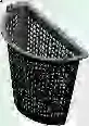
P178 · Grease chamber half-basket
Model / published specification
Size / compatibility
P178-300
300
T183 · Communication cable chamber
Model / published specification
Size / compatibility
T183-500×400
500×400
T183-840×450
840×450
T183-950×840
950×840
P173 · Cable chamber joint
Model / published specification
Size / compatibility
P173-300A×160B×110B
300A×160B×110B
P173-400A×100B×6
400A×100B×6
P173-600A×110B×12
600A×110B×12
LS08 · Communication chamber sealing ring
Model / published specification
Size / compatibility
LS08-500×400
500×400
P123 · Reducer joint with sealing ring
Model / published specification
Size / compatibility
P123-75B×80B
75B×80B
P123-110B×75B
110B×75B
P123-110B×115A
110B×115A
P123-110B×140B
110B×140B
P123-160B×110B
160B×110B
P123-160B×150A
160B×150A
P123-200B×110B
200B×110B
P123-200A×110B
200A×110B
P123-200A×150A
200A×150A
P123-200B×160B
200B×160B
P123-200A×160B
200A×160B
P123-200B×200A
200B×200A
P123-200A×200F
200A×200F
P123-200B×200D
200B×200D
P123-200A×200D
200A×200D
P123-200A×200B
200A×200B
P123-200B×210B
200B×210B
P123-200B×250B
200B×250B
P123-225A×150A
225A×150A
P123-225A×200B
225A×200B
P123-225A×200A
225A×200A
P123-225A×250B
225A×250B
P123-250B×110B
250B×110B
P123-250B×150A
250B×150A
P123-250B×160B
250B×160B
P123-250B×200A
250B×200A
P123-250B×200B
250B×200B
P123-250B×225A
250B×225A
P123-250B×270B
250B×270B
P123-250B×315B
250B×315B
P123-300A×200A
300A×200A
P123-300A×200B
300A×200B
P123-300A×225A
300A×225A
P123-300A×250B
300A×250B
P123-300A×300CII
300A×300CII
P123-300A×300F
300A×300F
P123-300A×300CI
300A×300CI
P123-300A×300D
300A×300D
P123-300A×315B
300A×315B
P123-315B×200B
315B×200B
P123-315B×200A
315B×200A
P123-315B×225A
315B×225A
P123-315B×250B
315B×250B
P123-315B×300D
315B×300D
P123-400A×200A
400A×200A
P123-400A×200B
400A×200B
P123-400B×200B
400B×200B
P123-400A×225A
400A×225A
P123-400A×250B
400A×250B
P123-400B×250B
400B×250B
P123-400A×300A
400A×300A
P123-400A×315B
400A×315B
P123-400B×315B
400B×315B
P123-400A×400E
400A×400E
P123-400A×400CI
400A×400CI
P123-400A×400F
400A×400F
P123-400B×400D
400B×400D
P123-400A×400D
400A×400D
P123-400A×400B
400A×400B
P123-400A×400CII
400A×400CII
P123-500A×300A
500A×300A
P123-500B×315B
500B×315B
P123-500A×400A
500A×400A
P123-500B×400B
500B×400B
P123-500A×500B
500A×500B
P123-500A×500CII
500A×500CII
P123-500A×500F
500A×500F
P123-500A×500CI
500A×500CI
P123-500A×500E
500A×500E
P123-500A×500D
500A×500D
P123-500B×500D
500B×500D
P123-600A×400B
600A×400B
P123-600A×400A
600A×400A
P123-600A×500B
600A×500B
P123-600A×500A
600A×500A
P123-600A×600E
600A×600E
P123-600A×600CII
600A×600CII
P123-600A×600F
600A×600F
P123-600A×600CI
600A×600CI
P123-600A×600D
600A×600D
P123-600A×600B
600A×600B
P123-600A×630B
600A×630B
P123-600A×700D
600A×700D
P123-700A×600A
700A×600A
P123-700A×700D
700A×700D
P123-700A×700E
700A×700E
P123-700A×700F
700A×700F
P123-700A×800D
700A×800D
P123-700A×800A
700A×800A
P123-800A×600A
800A×600A
P123-800A×700A
800A×700A
P123-800A×800F
800A×800F
P123-800A×800E
800A×800E
P123-800A×800D
800A×800D
P123-800A×830B
800A×830B
P123-800A×900B
800A×900B
P123-800A×900D
800A×900D
P123-800A×1000D
800A×1000D
P123-1000A×600A
1000A×600A
P123-1000A×700A
1000A×700A
P123-1000A×800A
1000A×800A
P123-1000A×1000D
1000A×1000D
P123-1000A×1000E
1000A×1000E
P123-1000A×1000F
1000A×1000F
P123-1000A×1100D
1000A×1100D
P123-1000A×1200D
1000A×1200D
P132 · Convergent chamber ring, internal insert
Model / published specification
Size / compatibility
P132-1000×700
1000×700
P132-1000×800
1000×800
P132-1200×700
1200×700
P132-1500×1000
1500×1000
P133 · Convergent chamber ring, external insert
Model / published specification
Size / compatibility
P133-1000×700
1000×700
P133-1000×800
1000×800
P133-1200×700
1200×700
P140 · Road surface gutter inlet
Model / published specification
Size / compatibility
P140-300×200-200
300×200-200
P140-420×290-315
420×290-315
P140-450×450-315
450×450-315
P140-650×350-400
650×350-400
P140-700×400-400
700×400-400
P141 · Side gutter inlet
Model / published specification
Size / compatibility
P141-420×290-315
420×290-315
P139 · Confluent reducer joint with sealing ring
Model / published specification
Size / compatibility
P139-200B×150A×110B
200B×150A×110B
P139-200B×160B×110B
200B×160B×110B
P139-250B×110B×3
250B×110B×3
P139-250B×150A×2
250B×150A×2
P139-315B×160B×160B×110B
315B×160B×160B×110B
P127 · End cap with sealing ring
Model / published specification
Size / compatibility
P127-225A
225A
P127-300A
300A
P127-400A
400A
P127-500A
500A
P127-600A
600A
P127-700A
700A
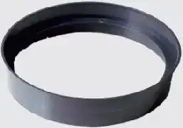
P127-800A
800A
P127-200B
200B
P127-250B
250B
P127-315B
315B
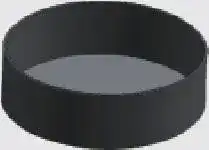
P128 · Upper retaining ring
Model / published specification
Size / compatibility
P128-700
700
P129 · Lower retaining ring
Model / published specification
Size / compatibility
P129-600
600
P129-700
700
P129-800
800
P131 · 45° elbow with sealing ring
Model / published specification
Size / compatibility
P131-300A
300A
P131-400A
400A
P131-500A
500A
P131-600A
600A
P131-800A
800A
P134 · Saddle joint
Model / published specification
Size / compatibility
P134-200×50B
200×50B
P134-200×75B
200×75B
P134-200×110B
200×110B
P134-315×75B
315×75B
P134-315×110B
315×110B
P134-315×150A
315×150A
P134-315×160B
315×160B
P134-315×200B
315×200B
P134-400/450×110B
400/450×110B
P134-400/450×160B
400/450×160B
P134-400/450×200A
400/450×200A
P134-400/450×200B
400/450×200B
P134-400/450×225A
400/450×225A
P134-400/450×250B
400/450×250B
P134-500×110B
500×110B
P134-500×160B
500×160B
P134-500×200A
500×200A
P134-500×200B
500×200B
P134-500×225A
500×225A
P134-500×250B
500×250B
P134-500×300A
500×300A
P134-500×315B
500×315B
P134-600/630×110B
600/630×110B
P134-600/630×160B
600/630×160B
P134-600/630×200A
600/630×200A
P134-600/630×200B
600/630×200B
P134-600/630×250B
600/630×250B
P134-700×110B
700×110B
P134-700×160B
700×160B
P134-700×200A
700×200A
P134-700×200B
700×200B
P134-700×225A
700×225A
P134-700×250A
700×250A
P134-700×300A
700×300A
P134-700×315B
700×315B
P147 · Heat-shrink tape for chamber base
Model / published specification
Size / compatibility
P147-248×200(200A)
248×200(200A)
P147-275×200(225A)
275×200(225A)
P147-375×200(300A)
375×200(300A)
P147-375×300(300A)
375×300(300A)
P147-505×200(400A)
505×200(400A)
P147-505×250(400A)
505×250(400A)
P147-505×300(400A)
505×300(400A)
P147-605×200(500A)
605×200(500A)
P147-605×250(500A)
605×250(500A)
P147-605×300(500A)
605×300(500A)
P147-605×400(500A)
605×400(500A)
P147-720×250(600A)
720×250(600A)
P147-720×300(600A)
720×300(600A)
P147-720×400(600A)
720×400(600A)
P147-840×400(800A)
840×400(800A)
P147-1005×250(800A)
1005×250(800A)
P147-1005×400(800A)
1005×400(800A)
P147-1005×450(800A)
1005×450(800A)
P147-1005×500(800A)
1005×500(800A)
P147-1005×600(800A)
1005×600(800A)
P147-1100×400(1000A)
1100×400(1000A)
P147-1100×450(1000A)
1100×450(1000A)
P147-1100×500(1000A)
1100×500(1000A)
P147-1153×300(1000A)
1153×300(1000A)
P147-1153×450(1000A)
1153×450(1000A)
P147-1153×500(1000A)
1153×500(1000A)
P147-215×150(200B)
215×150(200B)
P147-218×200(200B)
218×200(200B)
P147-265×200(250B)
265×200(250B)
P147-340×100(315B)
340×100(315B)
P147-340×200(315B)
340×200(315B)
P147-428×200(400B)
428×200(400B)
P147-428×300(400B)
428×300(400B)
P147-527×250(500B)
527×250(500B)
P147-1153×400(1000A)
1153×400(1000A)
P147-1640×500(1500B)
1640×500(1500B)
P146 · Heat-shrink tape for wellhole/base connection
Model / published specification
Size / compatibility
P146-215×100(200)
215×100(200)
P146-325×100(315)
325×100(315)
P146-421×100(400)
421×100(400)
P146-465×200(450)
465×200(450)
P146-526×100(500)
526×100(500)
P146-623×100(600)
623×100(600)
P146-650×100(630)
650×100(630)
P146-717×150(700)
717×150(700)
P146-820×150(800)
820×150(800)
P146-995×150(1000)
995×150(1000)
P146-1300×300(1200)
1300×300(1200)
P167 · Heat-shrink tape
Model / published specification
Size / compatibility
P167-505×250
505×250
P167-840×150
840×150
P167-1153×500
1153×500
P167-1250×500
1250×500
P167-1300×400
1300×400
P167-1500×150
1500×150
P167-1500×300
1500×300
P167-1520×200
1520×200
P167-1520×300
1520×300
P167-1600×500
1600×500
P167-1640×400
1640×400
P167-1800×300
1800×300
P167-1800×400
1800×400
P167-1800×450
1800×450
P167-1870×300
1870×300
P167-1870×450
1870×450
P151 · Chamber connection part
Model / published specification
Size / compatibility
P151-200
200
P151-300
300
P151-315
315
P151-400
400
P151-450
450
P151-500
500
P151-600
600
P151-700
700
P151-1000
1000
P151-1200
1200
P163 · Wellhole end cap
Model / published specification
Size / compatibility
P163-315
315
P163-400
400
P163-500
500
P163-600
600
P163-700
700
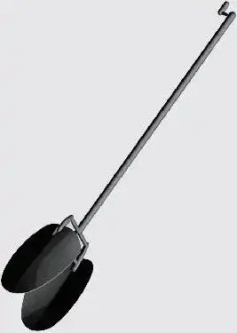
P156 · Cleaning tool
Model / published specification
Size / compatibility
P156-1M
1M
P156-1.5M
1.5M
P156-2M
2M
P156-2.5M
2.5M
P156-3M
3M
P156-3.5M
3.5M
P156-4M
4M
P156-4.5M
4.5M
P156-5M
5M
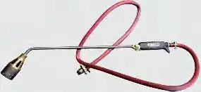
Liquefied-gas flame gun
Model / published specification
50
LS01 · Wellhole sealing ring
Model / published specification
Size / compatibility
LS01-315I
315I
LS01-315II
315II
LS01-400
400
LS01-450
450
LS01-500
500
LS01-600
600
LS01-700
700
LS01-800
800
LS01-800II
800II
LS01-1000
1000
LS01-1000II
1000II
P143 · Anti-drop chamber cover
Model / published specification
Size / compatibility
P143-500
500
P143-600
600
P143-700
700
P143-800
800
P175 · Cleanout
Model / published specification
Size / compatibility
P175-200×110B×75B
200×110B×75B
P154 · Mobile ladder
Model / published specification
Size / compatibility
P154-350×400I
350×400I
P155 · Stationary ladder
Model / published specification
Size / compatibility
P155-290×100I
290×100I
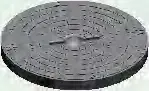
P170 · Composite circular cover
Model / published specification
Size / compatibility
P170-200
200
P170-315
315
P170-400
400
P170-450
450
P170-500
500
P170-600
600
P170-630
630
P170-700
700
P170-800
800
P170-1000
1000
P168 · Composite circular sewage cover
Model / published specification
Size / compatibility
P168-200
200
P168-315
315
P168-400
400
P168-450
450
P168-500
500
P168-600
600
P168-630
630
P168-700
700
P169 · Composite circular rainwater cover
Model / published specification
Size / compatibility
P169-200
200
P169-315
315
P169-400
400
P169-450
450
P169-500
500
P169-600
600
P169-630
630
P169-700
700
P177 · Cleanout well cover
Model / published specification
Size / compatibility
P177-200
200
P142 · Extension tube
Model / published specification
Size / compatibility
P142-200A
200A
P142-225A
225A
P142-250B
250B
P142-315B
315B
P179 · Lawn chamber cover with side gutter inlet
Model / published specification
Size / compatibility
P179-420×290-315
420×290-315
P148 · Circular lawn chamber cover
Model / published specification
Size / compatibility
P148-200
200
P148-315
315
P148-400
400
P148-450
450
P148-500
500
P148-600
600
P148-630
630
P148-700
700
P180 · Filter grid
Model / published specification
Size / compatibility
P180-160B
160B
P152 · Water grate
Model / published specification
Size / compatibility
P152-200
200
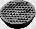
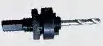
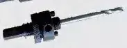
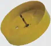
Tapper drill bit
Model / published specification
—
P150 · Tapper
Model / published specification
Size / compatibility
Opening Size (mm)
P150-75B
75B
90
P150-110B
110B
130
P150-直插110B
直插110B
110
P150-160B
160B
180
P150-200A
200A
255
P150-200B
200B
220
P150-直插200B
直插200B
200
P150-225A
225A
285
P150-250B
250B
270
P150-300A
300A
368
P150-315B
315B
345
P181 · Seven-hole wabbler joint
Model / published specification
Size / compatibility
P181-110B
110B
P171 · Adjustable-angle joint
Model / published specification
Size / compatibility
P171-160B
160B
P171-200B
200B
P171-225A
225A
P171-300A
300A
P124 · Chamber base adapter, external insert
Model / published specification
Size / compatibility
P124-315×400
315×400
P124-315×450
315×450
P124-315×500
315×500
P124-315×600
315×600
P124-315×700
315×700
P124-400×450
400×450
P124-400×500
400×500
P158-400×630
400×630
P124-400×600
400×600
P124-400×700
400×700
P124-500×600
500×600
P124-500×630
500×630
P124-500×700
500×700
P124-600×630
600×630
P124-600×700
600×700
P124-600×800
600×800
P124-600×1000
600×1000
P124-700×800
700×800
P124-700×1000
700×1000
P124-1000×1200
1000×1200
P157 · Chamber base adapter, internal insert
Model / published specification
Size / compatibility
P157-315×300
315×300
P157-315×400
315×400
P157-315×500
315×500
P157-315×600
315×600
P157-400×400
400×400
P157-400×500
400×500
P157-400×600
400×600
P157-500×500
500×500
P157-500×600
500×600
P157-600×600
600×600
P157-600×700
600×700
P157-700×700
700×700
P135 · One-way wellhole joint
Model / published specification
Size / compatibility
P135-315×225A
315×225A
P135-315×225A II
315×225A II
P135-315×250B
315×250B
P135-315×250B II
315×250B II
P135-400×300A
400×300A
P135-400×315B
400×315B
P135-400×400A
400×400A
P135-400×400B
400×400B
P135-700×400A
700×400A
P135-700×500A
700×500A
P135-700×600A
700×600A
P136 · Direct chamber connection
Model / published specification
Size / compatibility
P136-400×300A
400×300A
P136-400×315B
400×315B
P136-400×400A
400×400A
P136-400×400B
400×400B
P136-700×500A
700×500A
P136-700×600A
700×600A
P137 · Two-way convergence joint
Model / published specification
Size / compatibility
P137-315×110B×2
315×110B×2
P137-400×110B×2
400×110B×2
P137-400×160B×2
400×160B×2
P138 · Tee convergence joint
Model / published specification
Size / compatibility
P138-315×110B×3
315×110B×3
P138-400×110B×3
400×110B×3
P138-400×160B×3
400×160B×3
P158 · Five-way convergence joint
Model / published specification
Size / compatibility
P158-400×160B×5
400×160B×5
LS02 · Straight sealing ring for HDPE double-wall pipe
Model / published specification
Size / compatibility
LS02-110B
110B
LS02-160B
160B
LS02-225A
225A
LS02-300A
300A
LS02-400A
400A
LS02-500A
500A
LS02-600A
600A
LS02-700A
700A
LS02-800A
800A
LS02-N225
N225
LS02-N200-SN4
N200-SN4
LS02-N200-SN8
N200-SN8
LS02-N300-SN4
N300-SN4
LS02-N300-SN8
N300-SN8
LS02-N400-SN4
N400-SN4
LS02-N400-SN8
N400-SN8
LS02-N500-SN4
N500-SN4
LS02-N500-SN8
N500-SN8
LS02-N600-SN8
N600-SN8
LS02-N600-SN4
N600-SN4
LS03 · PVC-U double-wall pipe sealing ring
Model / published specification
Size / compatibility
LS03-110B
110B
LS03-160B
160B
LS03-200B
200B
LS03-250B
250B
LS03-315B
315B
LS03-400B
400B
LS03-500B
500B
LS07 · Side pipe sealing ring
Model / published specification
Size / compatibility
LS07-110B
110B
LS07-160B
160B
LS05 · Reducer joint sealing ring
Model / published specification
Size / compatibility
LS05-200B
200B
LS05-250B/225A
250B/225A
LS05-400B
400B
LS05-500B
500B
LS09 · Electrofusion PE KRAH spigot sealing ring
Model / published specification
Size / compatibility
LS09-200A
200A
LS09-300A
300A
LS09-400A
400A
LS09-500A
500A
LS09-600A
600A
LS09-700A
700A
LS09-800A
800A
LS09-1000A
1000A
PE spiral structured-wall gasket socket (spigot)
Model / published specification
200A
300A
400A
500A
600A
700A
800A
1000A
1200A
1400A
PE spiral structured-wall gasket socket (socket)
Model / published specification
200A
300A
400A
500A
600A
700A
800A
1000A
1200A
1400A
Multifunction PE gasket socket (spigot)
Model / published specification
200A
300A
400A
500A
600A
800A
1000A
1200A
Multifunction PE gasket socket (socket)
Model / published specification
200A
300A
400A
500A
600A
800A
1000A
1200A
Parentheses in heat-shrink specifications state the compatible connection size. The source lists P158-400×630 inside the external-adapter table; that designation is retained. In tapper models, 直插 denotes direct-insert. Blank drill-bit specifications remain unspecified.
Unpowered wastewater purification tank: 5-person model
Parameter name
Value
Design population
5
Daily wastewater volume
1.0 m³/day
First anaerobic chamber
0.826 m³
Second anaerobic chamber
0.682 m³
Filter pipes volume
0.013 m³
Water-modulation tank
0.156 m³
Disinfection tank
0.011 m³
Total capacity
1.688 m³
Main body material
PP
Body plate thickness
5.0–10 mm
Filter shape
Net-like coil
Filter material
PP
Filtration media shape
Fiber
Filtration media material
PP
Advection-mouth balls
Ø96 PP balls
Access cover material
Resin concrete or cast iron
Access openings
Ø315 ×2 / Ø400 ×1
Maximum diameter
1600 mm
Height
1725 mm
Inlet pipe bottom dimension
300 mm
Outlet pipe bottom dimension
500 mm
Weight
180 kg
The PP wastewater tank uses anaerobic treatment, filtration and disinfection without an electric blower or pump. Grease chambers collect oily wastewater for cleaning; the catalogue reports oil separation above 90%. Cable chambers use PPB copolymer, with a 250 mm telescopic ring and 200 mm height modules. The catalogue lists PPB melting at 164–170°C and brittle temperature −35°C; the PE option is listed at −70°C.
General engineering data
Source: catalogue printed pages 5–6. All elevations are in mm; A/B nominal-size series follow the source. Blank source cells remain —. These are component effective heights, not installation depth.
Negative-pressure tests on municipal and residential monolithic chamber structures; external water-pressure test; guide-trough deformation recording.
Load paths: A groundwater buoyancy; B soil shear on branches; C impact on the base; D radial pressure on the shaft; E vehicle and surcharge load.
Source: printed pp7–8. The source identifies these test types but gives no test-method standard numbers, loads or acceptance limits in this chapter.
Catalogue comparison
Source: printed pp9–12. These are manufacturer comparison claims and historical source estimates, not a quotation for installation in Armenia. Costs are CNY; the economic example is for 10 chambers.
Parameter name
Plastic chamber
Brick chamber
Reinforced concrete chamber
Construction speed
≥20 units/day
5 units/day
2 units/day
Corrosion resistance
Acid and corrosion resistant
Not acid/corrosion resistant
Acid and corrosion resistant
Connection
Flexible; settlement with pipes
Rigid
Rigid
Vibration resistance
High
Low
Medium
Drainage
Smooth guide trough
Cement rendering; high internal resistance
Concrete; internal resistance
Service life
≥50 years
5–10 years
40 years
Footprint / excavation
Small
Large
Large
Workers (10 chambers)
2
2
2
Construction time (10 chambers)
0.5 day
2 days
5 days
Labour cost (10 chambers)
100 CNY
400 CNY
1000 CNY
Overall cost
Low
High
High
Let’s find the right solution
Contact LESSO Armenia for pricing, options, sizes and delivery.
 ARMENIA