 ARMENIA
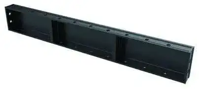
UE rod-tie aluminium formwork
Four coordinated subsystems: panels, supports, reinforcement and accessories. Powder-coated aluminium components and galvanised steel accessories.
Explore individual product photographs, size variants and technical data directly on this page.
Four coordinated subsystems: panels, supports, reinforcement and accessories. Powder-coated aluminium components and galvanised steel accessories.
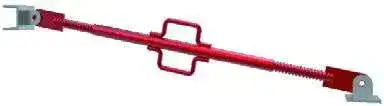
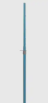
Props, braces, beam supports and early-striking heads support slabs and beams. The catalogue describes 4–5-day floor cycles and tested vertical allowable loading of 20–25 kPa for its supporting system.
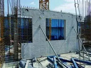
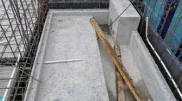
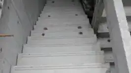
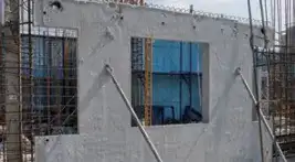
Factory-made floor panels, caissons, beams, stairs, walls and bay windows, connected with the cast-in-place structure according to the structural design.
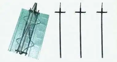
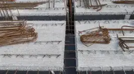
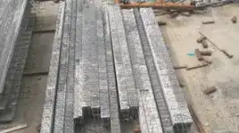
TDA and TDB truss-deck systems. TDB uses one top chord, two bottom chords and welded web bars on profiled galvanised steel; the deck acts as permanent formwork during concrete pouring.
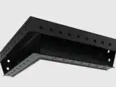
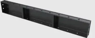
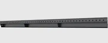
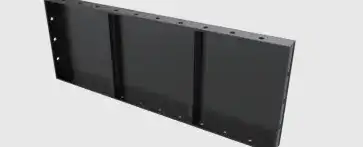
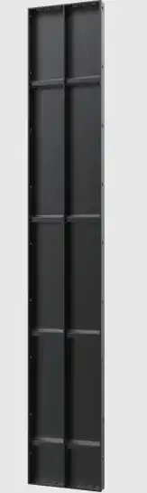
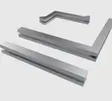
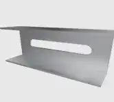
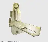
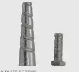
Extruded aluminium profiles include6061-T6. Flat wall, slab, beam and soffit panels connect through corner elements to form the closed concrete mould. Surface-treated aluminium and galvanised steel accessories are used.
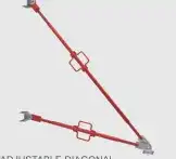
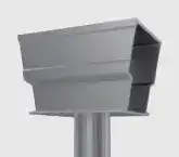
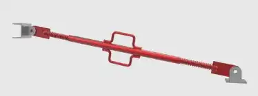
Props, prop heads, beam supports and adjustable diagonal braces support slabs, beam soffits and suspended beams. Braces adjust in three dimensions and control wall/column alignment. The catalogue reports4–5days per floor and20–25kPa tested permissible vertical support pressure; these are system/project conditions, not a universal rating for each prop.
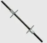
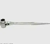
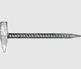
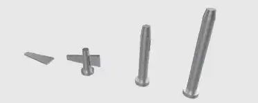
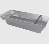
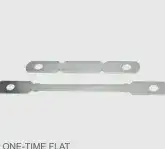
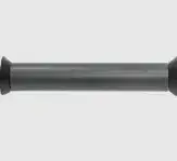
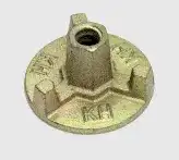
For normal2.8–3.2m storeys, the catalogue arrangement uses four waler tiers internally and five externally, with local reinforcement at openings and bay windows. Walers control flatness; ties control section width. Install in the numbered sequence and dismantle in reverse order using the specified tools. Pins and wedges connect panels; sleeves and ties provide fixing passages.

| Operation | Days |
|---|---|
| Survey and setting out | 0.5 |
| Wall/column reinforcement and M&E installation | 0.5 |
| Wall/column panel installation | 1 |
| Slab and beam panel installation | 1 |
| Beam/slab reinforcement and M&E installation | 1 |
| Concrete casting | 0.5 |
| Wall/column panel dismantling | 0.5 |
| Beam/slab panel dismantling; props retained | 0.5 |
The A/B work-section programme overlaps operations to achieve the illustrated four-day floor cycle. Retain props during early stripping; work and lifting arrangements follow the project engineering plan.
| Inspection item | Tolerance (mm) |
|---|---|
| Section size | −3…+3 |
| Surface flatness | 0…5 |
| Verticality | 0…5 |
| Internal/external corners | 0…3 |
| Net height | −10…+10 |
| Slab horizontal level | 0…5 |
Inspect for smooth, uniformly coloured surfaces without cracks, honeycombing, pitting, exposed reinforcement or formwork explosions. Panel joints should show no visible concrete grout leakage.
Contact LESSO Armenia for pricing, options, sizes and delivery.
Original PDF files